Featured Post Today
print this page
Latest Post

Minimalist Oscilloscope

Circuit diagram: 
Description

If you are the proud owner of an old oscilloscope tube, you may be interested in using it once more for its original purpose. All you need are the right voltages on the right pins: in practice you may need to peer closely inside to find out which pins on the base correspond to the acceleration and deflection electrodes, in particular if there is no part number to be seen on the tube. The tube we had for experimental purposes was a 7 cm model of unknown provenance.
So the first step is to establish which pins correspond to the heater, cathode, grids, deflection plates, and anode. With this done we can make our simple oscilloscope as follows: connect the Y input via a suitable capacitor to one of the Y deflection plates; for X deflection we use a neon lamp oscillator to generate a timebase; and with a focus regulator circuit we have a complete oscilloscope.
Operation of the horizontal deflection oscillator is visible as the gentle flickering of the neon lamp. Whenever the voltage across the parallel-connected capacitor reaches the strike voltage of the lamp, it is discharged with a brief pulse of current. It is hard to imagine a simpler way to generate a sawtooth waveform. The supply voltage of 300 V is adequate for simple experiments, even if the tube is rated for operation at 1000 V or even more.
Now, if a signal is applied to the Y input, we should be able to see the waveform on the screen. It must be admitted that the design’s sensitivity, linearity, trace size, bandwidth and triggering facilities leave a little to be desired. Nevertheless we have shown how little circuitry is required to make a real working oscilloscope.
  
0 comments

Fuse Monitor Circuit Diagram

This circuit monitors a DC fuse. Its LED lights continously when the fuse is intact but blinks is the fuse is broken. The fuse monitor circuit is designed for 12 volts but can be modified for other voltages. To use this circuit for 6 volts, divide all resistance values by two, for 24 volts, double the values.
The circuit consumes around 25 mA and most of the current is consumed by the LED. If you decide to use the circuit in battery operated modules, it is highly recommended to use a high efficiency LED and increase the value of R7 accordingly.
0 comments

High Quality Intercom Circuit Diagram

Description:
A very high quality intercom, which may also be used for room monitoring.
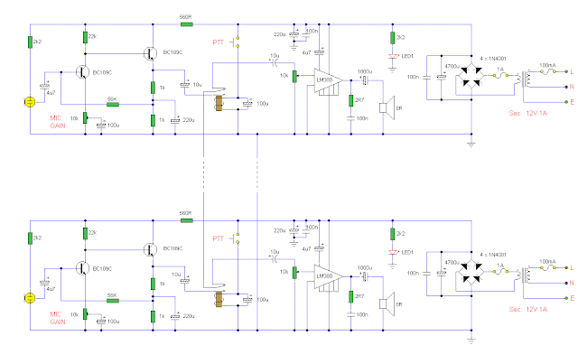
Circuit diagram
Notes:
This circuit consists of two identical intercom units. Each unit contains a power supply, microphone preamplifier, audio amplifier and a Push To Talk (PTT) relay circuit. Only 2 wires are required to connect the units together. Due to the low output impedance of the mic preamp, screened cable is not necessary and ordinary 2 core speaker cable, or bell wire may be used.
The schematic can be broken into 34 parts, power supply, mic preamp, audio amplifierand PTT circuit. The power supply is designed to be left on all the time, which is why no on / off switch is provided. A standard 12 V RMS secondary transformer of 12VA will power the unit. Fuses are provided at the primary input and also secondary, before the rectifier. The 1 A fuse needs to be a slow blow type as it has to handle the peak rectifier current as the power supply electrolytics charge from zero volts.
The microphone amplifier is a 2 transistor direct coupled amplifier. BC108B transistors will work equally well in place of the BC109C transistors. The microphone used is a 3 terminal electret condenser microphone insert. These are popular and require a small current to operate. The preamp is shown in my audio circuit section as well, but has a very high gain and low distortion. The last transistor is biased to around half the supply voltage; this provides the maximum overload margin for loud signals or loud voices. The gain may be adjusted with the 10k preset. Sensitivity is very high, and a ticking clock can easily be heard from the distant loudspeaker.
The amplifier is based on the popular National Semiconductor LM380. A 50 mV input is all thats required to deliver 2W RMS into an 8 ohm loudspeaker. The choice of loudspeaker determines overall sound quality. A small loudspeaker may not produce a lot of bass, I used an old 8 inch radio loudspeaker. The 4.7u capacitor at pin 1 of the LM380 helps filter out any mains hum on the power supply. This can be increased to a 10u capacitor for better power supply rejection ratio.
The push to talk (PTT) circuit is very simple. A SPDT relay is used to switch between mic preamplifier output or loudspeaker input. The normally closed contact is set so that each intercom unit is "listening". The non latching push button switch must be held to talk. The 100u capacitor across the relay has two functions. It prevents the relays back emf from destroying the semiconductors, and also delays the release of the relay. This delay is deliberate, and prevents any last word from being "chopped" off.
Setting Up and Testing:
This circuit does not include a "call" button. This is simply because it is designed to be left on all the time, someone speaking from one unit will be heard in the other, and vice versa. Setup is simple, set to volume to a comfortable level, and adjust the mic preset while speaking with "normal volume" from one meter away. You do not need to be in close contact with the microphone, it will pick up a conversation from anywhere in a room. If the units are a long way away, there is a tendency for the cable to pick up hum, or radio interference. There are various defenses against this. One way is to use a twisted pair cable, each successive turn cancels the interference from the turn before. Another method is to use a small capacitor of say 100n between the common terminal of each relay and ground. This shunts high frequency signals to earth. Another method is to use a low value resistor of about 1k. This will shunt interference and hum, but will shunt the speech signal as well. However as the output impedance of each mic preamp is low, and the speech signals are also low, this will have little effect on speech but reduce interference to an acceptable level.
IC Pinout:
The LM380 pinout viewed from above is shown below on the left. In the schematic, the LM380 has been represented as a triangle, the pins are shown on the right hand diagram. Pins marked "NC" have no connection and are not used.
PCB Layout:
Corey Rametta has kindly drafted a PCB layout for this project. First an oversized version to show component placement. Note the tracks on the bottom side, components on the top side.
 Below is the actual size version shown track side.

Author: Andy Collinson
E-mail: anc@mitedu.freeserve.co.uk
Source: http://www.zen22142.zen.co.uk
0 comments

Voltage Doubler Circuit

Circuit Diagram
Schematic Diagram for a Voltage Doubling Circuit (capacitor values are in microF)

This is a circuit that outputs a voltage Vout that is approximately twice the level of the Vcc voltage.
   
The circuit uses a 555 timer IC configured as an astable multivibrator, i.e., it generates a continuous square wave signal of a set frequency as long as its reset pin (pin 4) is held high.  This means that the 555 output toggles between '1' and '0' continuously at the set frequency.
   
When the circuit is powered up and the 555 output (pin 3) goes to logic '1' for the very first time, its near-Vcc voltage level causes C3 to charge up through D2 and also reach near-Vcc level. When the output goes to logic '0', C2 charges from Vcc through D1, also to a near-Vcc level.  When the 555 output goes back to logic '1' again, C3 may still have some (if not most) of its charge left, and will allow to charge up to a higher level since it is now effectively in parallel with the series circuit of the 555 level '1' output and the charged C2. 
  
After several cycles of C2 and C3 alternately charging, C3 will subsequently build up a voltage level equal to almost twice the Vcc level. This C3 voltage comes from the charge pumped in by the sum of the C2 voltage (near-Vcc) and the 555 output voltage when it is at logic '1' (also near-Vcc). At this point, the output Vout of the circuit will already be almost twice the Vcc level.

Source  http://www.ecelab.com/circuit-doubler.htm
1 comments

LED Traffic Lights

Description 
 The LED traffic Light circuit controls 6 LEDs (red, yellow and green) for both north/south directions and east/west directions. The timing sequence is generated using a CMOS 4017 decade counter and a 555 timer. Counter outputs 1 through 4 are wire ORed using 4 diodes so that the (Red - North/South) and (Green - East/West) LEDs will be on during the first four counts. The fifth count (pin 10) illuminates (Yellow - East/West) and (Red - North/South). Counts 6 through 9 are also wire ORed using diodes to control (Red - East/West) and (Green - North/South). Count 10 (pin 11) controls (Red - East/West) and (Yellow - North/South). The time period for the red and green lamps will be 4 times longer than for the yellow and the complete cycle time can be adjusted with the 47K resistor. The eight 1N914 diodes could be subsituted with a dual 4 input OR gate (CD4072). 
0 comments

Frequency Divider 2 Circuit

Description 
 This is a classic divider of frequency via two. It is achieved with a classic circuit T-flipFlop, round IC1 [ 4011 ]. In the circuit, the frequency of network, after are limit the negative half-s period of sine wave and transform in square wave, are divided via two. Thus for frequency50 HZ, we will take in the exit pulse of frequency 25 HZ. The supply of circuit it is + 5V and does not need high benefit in current.
Circuit diagram 


Part list
  • R1= 10Kohm
  • R2= 100Kohm
  • R3= 680 ohm
  • R4= 1Mohm
  • R5-6-7= 100Kohm
  • R8= 47 ohm
  • R9-10-11= 100Kohm
  • C1= 1000uF 25V
  • C2-3= 100nF 100V ceramic
  • C4-5= 100pF ceramic
  • IC1= 4011
  • T1= 110/220Vac //8V 100mA
  • D1-2= 1N4007
  • D3= 5.1V 0.5W Zener
  • D4-5= 1N4148 
Source -http://users.otenet.gr/~athsam/frequency_divider.htm
0 comments

Automatic Loudness Control

Circuit diagram:

Parts
  • P1 10K Linear Potentiometer (Dual-gang for stereo)
  • R1,R6,R8 100K 1/4W Resistors
  • R2 27K 1/4W Resistor
  • R3,R5 1K 1/4W Resistors
  • R4 1M 1/4W Resistor
  • R7 20K 1/2W Trimmer Cermet
  • C1 100nF 63V Polyester Capacitor
  • C2 47nF 63V Polyester Capacitor
  • C3 470nF 63V Polyester Capacitor
  • C4 15nF 63V Polyester Capacitor
  • C5,C9 1µF 63V Electrolytic or Polyester Capacitors
  • C6,C8 47µF 63V Electrolytic Capacitors
  • C7 100pF 63V Ceramic Capacitor
  • IC1 TL072 Dual BIFET Op-Amp
  • SW1 DPDT Switch (four poles for stereo)
Comments:
 In order to obtain a good audio reproduction at different listening levels, a different tone-controls setting should be necessary to suit the well known behaviour of the human ear. In fact, the human ear sensitivity varies in a non-linear manner through the entire audible frequency band, as shown by Fletcher-Munson curves. A simple approach to this problem can be done inserting a circuit in the preamplifier stage, capable of varying automatically the frequency response of the entire audio chain in respect to the position of the control knob, in order to keep ideal listening conditions under different listening levels. Fortunately, the human ear is not too critical, so a rather simple circuit can provide a satisfactory performance through a 40dB range. The circuit is shown with SW1 in the "Control-flat" position, i.e. without the Automatic Loudness Control. In this position the circuit acts as a linear preamplifier stage, with the voltage gain set by means of Trimmer R7. Switching SW1 in the other position the circuit becomes an Automatic Loudness Control and its frequency response varies in respect to the position of the control knob by the amount shown in the table below. C1 boosts the low frequencies and C4 boosts the higher ones. Maximum boost at low frequencies is limited by R2; R5 do the same at high frequencies.
Technical data: 
 Frequency response referred to 1KHz and different control knob positions:
Total harmonic distortion at all frequencies and 1V RMS output: < 0.01%
Notes: 

  • SW1 is shown in "Control flat" position.
  • Schematic shows left channel only, therefore for stereo operation all parts must be doubled except IC1, C6 and C8.
  • Numbers in parentheses show IC1 right channel pin connections.
  • R7 should be set to obtain maximum undistorted output power from the amplifier with a standard music programme source and P1 rotated fully clockwise. 
 Author: RED Free Circuit Designs
Source http://www.redcircuits.com/
0 comments

A Very Useful Timed Beeper Circuit Schematic

Description 
This circuit is intended for alerting purposes after a certain time is elapsed. It is suitable for table games requiring a fixed time to answer a question, or to move a piece etc. In this view it is a modern substitute for the old sandglass. Useful also for time control when children are brushing teeth (at least two minutes!), or in the kitchen, and so on. 
Circuit diagram:
Parts:
  • R1 = 220R
  • R2 = 10M
  • R3 = 1M
  • R4 = 10K
  • R5 = 47K
  • C1 = 100nF-63V
  • C2 = 22µF-25V
  • D1 = 1N4148
  • D2 = 3mm. Red LED
  • Q1 = BC337
  • P1 = SPST Pushbutton (Start)
  • P2 = SPST Pushbutton (Reset)
  • PS = Piezo sounder (incorporating 3KHz oscillator)
  • B1 = 3V Battery (2 AA 1.5V Cells in series)
  • IC1 = CD4081 Quad 2 input AND Gate IC
  • IC2 = CD4060 14 stage ripple counter and oscillator IC
  • SW1 = 4 ways Switch (See notes)
Circuit Operation:

Pushing on P1 resets IC2 that start oscillating at a frequency fixed by R3 & C1. With values shown, this frequency is around 4Hz. LED D2, driven by IC1A & B, flashing at the same oscillator frequency, will signal proper circuit operation. SW1 selects the appropriate pin of IC2 to adjust timing duration:
  • Position 1 = 15 seconds
  • Position 2 = 30 seconds
  • Position 3 = 1 minute
  • Position 4 = 2 minutes
When the selected pin of IC2 goes high, IC1C drives Q1 and the piezo sounder beeps intermittently at the same frequency of the LED. After around 7.5 seconds pin 4 of IC2 goes high and IC1D stops the oscillator through D1. If you want to stop counting in advance, push on P2. 

Notes: 
  1. SW1 can be any type of switch with the desired number of ways. If you want a single fixed timing duration, omit the switch and connect pins 9 & 13 of IC1 to the suitable pin of IC2.
  2. The circuit's reset is not immediate. Pushing P2 forces IC2 to oscillate very fast, but it takes some seconds to terminate the counting, especially if a high timer delay was chosen and the pushbutton is operated when the circuit was just starting. In order to speed the reset, try lowering the value of R5, but pay attention: too low a value can stop oscillation.
  3. Frequency operation varies with different brand names for IC2. E.g. Motorola's ICs run faster, therefore changing of C1 and/or R3 values may be necessary.
  4. You can also use pins 1, 2, 3 of IC2 to obtain timings of 8, 16 and 32 minutes respectively.
  5. An on-off switch is not provided because when off-state the circuit draws no significant current
Source  http://www.extremecircuits.net/2009/12/very-useful-timed-beeper-circuit.html
0 comments

Speech Filter

Description 
The human speech apprehend a small area of frequencies, that is extended from 300HZ until 3KHZ. This spectrum is also internationally recognized for the transmission of speech via telecommunications networks. This is also the mainer use of this circuit, one and it can be used in uses that we needed this concrete spectrum of frequencies, rejecting the spectrum on and under what, making comprehensible the speech. The circuit is constituted by two active units, filters of second class (calculated for critical damping). The first filter round the IC1A rejects the low frequencies (under 300 HZ) [high pass] and the second IC1B high (above 3KHZ) [low pass], composing thus a total filter band pass of area (300HZ-3kHZ). In order to has good yield the filter, as with all the filters, it should are used resistances metal film 1% and capacitors polysteryne. 
Circuit diagram
Part List
  • R1= 120Kohm
  • R2= 100Kohm
  • R3= 470Kohm
  • R4-7= 8.2Kohm
  • R5= 6.8Kohm
  • R6= 33Kohm
  • R7= 150Kohm
  • R8= 47Kohm
  • C1-2-8= 2.2nF 100V polystyrene
  • C3= 150pF
  • C4-9= 100nF 100V
  • C5-10= 47uF 25V
  • C6= 100nF 100V polystyrene
  • C7= 560pF
  • C11= 150pF
  • C12= 10uF 25V
  • IC1= TL072 
 Source http://users.otenet.gr/~athsam/speetch_filter.htm
1 comments

QRP antenna tuner circuit

Description.
Low power ( 3 to 30 MHz)  transmitters constructed by hams are generally called QRP’s. For such transmitters a well tuned antenna is a must.If the impedance is not properly matched there will be a little or no output.But if properly matched there will be great results.A circuit for matching the antenna properly with the transmitter id given below.
The output of the transmitter is given to the input of the tuner( connector BNC1). The output of the tuner(connector BNC2) must be connected to antenna.Then adjust the L1 and C1 to obtain the maximum transmission power.The transmission power can be checked using a SWR meter.
Circuit diagram with Parts list. 
 

Notes. 
  • Assemble the circuit on a goos quality PCB or common board.
  • If the matching is not satisfactory then change the values of L1,C1,C2&C3  to the next close value and tune again.
  • Proper tuning requires some trial and error.
  • The circuit can be enclosed in an aluminum casing for better performance.
Source -  http://www.circuitstoday.com/qrp-antenna-tuner-circuit
0 comments

Zero degree Celsius alarm

Description.
This simple circuit will produce an alarm whenever the temperature falls below zero degree. A thermistor is used here to sense temperature. The op-amp LM7215 is used to compare the reference voltage and voltage from the thermistor network. Reference voltage is given to the non inverting input (pin3) of the IC and voltage from thermistor network is given to the inverting input (pin4).When temperature becomes less than zero degree the voltage at the non inverting input becomes larger than the voltage at the inverting input and the output of the op-amp becomes high. This makes the transistor Q1 ON and drives the piezo buzzer to make the alarm. In the power supply section, IC 7805 is used to derive 5V from the 9V battery.
Circuit diagram with Parts list.
 Power supply for this circuit.


Notes.
  • Assemble the circuit on a good quality PCB.
  • The thermistor used here is a glass bead thermistor, type No: KEYSTONE RL0503-5536K-122-MS (361K @ 0 degree Celsius and 100K @ 25 degree Celsius).
  • The IC1 must be mounted on a holder.
  • The battery B1 can be a 9V PP3 battery.

Source - http://www.circuitstoday.com/zero-degree-celsius-alarm
0 comments

Automatic Windshield Washer Control

Description 
Most, if not all, recent cars have an impressive amount of electronics, whether it be ABS brake systems, engine control with injection calculators, airbag activation, or other various functions, called comfort functions. Among them is one which we tend to forget because it has become so common today. It turns on the windshield wipers automatically for a few seconds after the windshield cleaner. This practice is almost indispensable because it avoids any dripping of excess rinse product right in the middle of a just-cleaned windshield.
Unfortunately, many ‘low end’ cars or some of the older cars are not equipped with this automatic function which is a very nice convenience to have. So, since all that is required is a handful of components that any electronics hobbyist worthy of the name already has in his/her drawer, we will discuss the circuit proposed here. This project is super simple and simply keeps the windshield wiper activated for a few seconds after the windshield washer control contact has been released.
While the windshield washer pump is operating, the 12 volts delivered by the battery are present at the terminals and are therefore charging capacitor C1. Once the windshield washer has stopped, this capacitor can only discharge through R2, P1, R3, and the T1 emitter-base junction, due to the presence of diode D1. It thus keeps T1 in the conductive state during a certain time, the exact period of which depends on the setting of P1. T1 in turn saturates T2, which then does the same for T3. 
Circuit diagram:

The Re1 relay is therefore connected which maintains the windshield wiper in operation because its work contact is wired in parallel to the control switch. Once C1 is sufficiently discharged, T1 is blocked, which then blocks T2 and T3 and deactivates relay Re1. The type of components is not really critical, even if we indicate specific reference numbers for T3, any low-power npn transistor with a gain over 25 will work. However, considering the amount of power consumed by the windshield wiper motor, relay Re1 will imperatively be an ‘automobile’ relay.
You can find very low-priced ones at many car accessory shops (and even at some component retailers). These relays maintain contact under 12 volts and often do not have more than one work contact but they are, in general, capable of cutting off about 20 amps. Finally, the only delicate point of this project is to properly identify the control wire for the windshield pump on one hand, and the windshield wiper motor on the other. Observing what is happening at the various connections with a simple voltmeter, should get it right without too much difficulty.
Author: Christian Tavernier, Elektor Electronics
Source http://www.extremecircuits.net/2010/05/automatic-windshield-washer-control.html
1 comments

Mini High-Voltage Generator

Circuit diagram:
Description
 Here’s a project that could be useful this summer on the beach, to stop anyone touching your things left on your beach towel while you’ve gone swimming; you might equally well use it at the office or workshop when you go back to work. In a very small space, and powered by simple primary cells or rechargeable batteries, the proposed circuit generates a low-energy, high voltage of the order of around 200 to 400 V, harmless to humans, of course, but still able to give a quite nasty ‘poke’ to anyone who touches it.
Quite apart from this practical aspect, this project will also prove instructional for younger hobbyists, enabling them to discover a circuit that all the ‘oldies’ who’ve worked in radio, and having enjoyed valve technology in particular, are bound to be familiar with. As the circuit diagram shows, the project is extremely simple, as it contains only a single active element, and then it’s only a fairly ordinary transistor. As shown here, it operates as a low-frequency oscillator, making it possible to convert the battery’s DC voltage into an AC voltage that can be stepped up via the transformer.
Using a centre-tapped transformer as here makes it possible to build a ‘Hartley’ oscillator around transistor T1, which as we have indicated above was used a great deal in radio in that distant era when valves reigned supreme and these was no sign of silicon taking over and turning most electronics into ‘solid state’. The ‘Hartley’ is one of a number of L-C oscillator designs that made it to eternal fame and was named after its invertor, Ralph V.L Hartley (1888-1970). For such an oscillator to work and produce a proper sinewave output, the position of the intermediate tap on the winding used had to be carefully chosen to ensure the proper step-down (voltage reduction) ratio.
Here the step-down is obtained inductively. Here, optimum inductive tapping is not possible since we are using a standard, off-the-shelf transformer. However we’re in luck — as its position in the centre of the winding creates too much feedback, it ensures that the oscillator will always start reliably. However, the excess feedback means that it doesn’t generate sinewaves; indeed, far from it. But that’s not important for this sort of application, and the transformer copes very well with it.
The output voltage may be used directly, via the two current-limiting resistors R2 an R3, which must not under any circum-stances be omitted or modified, as they are what make the circuit safe. You will then get around 200 V peak-to-peak, which is already quite unpleasant to touch. But you can also use a voltage doubler, shown at the bottom right of the figure, which will then produce around 300 V, even more unpleasant to touch. Here too of course, the resistors, now know as R4 and R5, must always be present. The circuit only consumes around a few tens of mA, regardless of whether it is ‘warding off’ someone or not! If you have to use it for long periods, we would however recommend powering it from AAA size Ni-MH batteries in groups of ten in a suitable holder, in order not to ruin you buying dry batteries. 
Warning!
If you build the version without the voltage doubler and measure the output voltage with your multimeter, you’ll see a lower value than stated. This is due to the fact that the waveform is a long way from being a sinewave, and multimeters have trouble interpreting its RMS (root-mean-square) value. However, if you have access to an oscilloscope capable of handling a few hundred volts on its input, you’ll be able to see the true values as stated.
To use this project to protect the handle of your beach bag or your attachecase, for example, all you need do is fix to this two small metallic areas, quite close together, each connected to one output terminal of the circuit. Arrange them in such a way that unwanted hands are bound to touch both of them together; the result is guaranteed! Just take care to avoid getting caught in your own trap when you take your bag to turn the circuit off!

Author: Elektor Electronics 2008
Source http://www.extremecircuits.net/2010/05/mini-high-voltage-generator.html
1 comments

3W FM Transmitter Circuit Diagram

Description
This is the schematic for an FM transmitter with 3 to 3.5 W output power that can be used between 90 and 110 MHz. Although the stability isn't so bad, a PLL can be used on this circuit.
This is a circuit that I've build a few years ago for a friend, who used it in combination with the BLY88 amplifier to obtain 20 W output power. From the notes that I made at the original schematic, it worked fine with a SWR of 1 : 1.05 (quite normal at my place with my antenna).
Circuit diagram
 
Parts:
R1,R4,R14,R15 10K 1/4W Resistor
R2,R3 22K 1/4W Resistor
R5,R13 3.9K 1/4W Resistor
R6,R11 680 Ohm 1/4W Resistor
R7 150 Ohm 1/4W Resistor
R8,R12 100 Ohm 1/4W Resistor
R9 68 Ohm 1/4W Resistor
R10 6.8K 1/4W Resistor
C1 4.7pF Ceramic Disc Capacitor
C2,C3,C4,C5,C7,C11,C12 100nF Ceramic Disc Capacitor
C6,C9,C10 10nF Ceramic Disc Capacitor
C8,C14 60pF Trimmer Capacitor
C13 82pF Ceramic Disc Capacitor
C15 27pF Ceramic Disc Capacitor
C16 22pF Ceramic Disc Capacitor
C17 10uF 25V Electrolytic Capacitor
C18 33pF Ceramic Disc Capacitor
C19 18pF Ceramic Disc Capacitor
C20 12pF Ceramic Disc Capacitor
C21,C22,C23,C24 40pF Trimmer Capacitor
C25 5pF Ceramic Disc Capacitor
L1 5 WDG, Dia 6 mm, 1 mm CuAg, Space 1 mm
L2,L3,L5,L7,L9 6-hole Ferroxcube Wide band HF Choke (5 WDG)
L4,L6,L8 1.5 WDG, Dia 6 mm, 1 mm CuAg, Space 1 mm
L10 8 WDG, Dia 5 mm, 1 mm CuAg, Space 1 mm
D1 BB405 or BB102 or equal (most varicaps with C = 2-20 pF [approx.] will do)
Q1 2N3866
Q2,Q4 2N2219A
Q3 BF115
Q5 2N3553
U1 7810 Regulator
MIC Electret Microphone
MISC PC Board, Wire For Antenna, Heatsinks

Notes:
1. Email Rae XL Tkacik with questions, comments, etc.
2. The circuit has been tested on a normal RF-testing breadboard (with one side copper). Make some connections between the two sides. Build the transmitter in a RF-proof casing, use good connectors and cable, make a shielding between the different stages, and be aware of all the other RF rules of building.
3. Q1 and Q5 should be cooled with a heat sink. The case-pin of Q4 should be grounded.
4. C24 is for the frequency adjustment. The other trimmers must be adjusted to maximum output power with minimum SWR and input current.
5. Local laws in some states, provinces or countries may prohibit the operation of this transmitter. Check with the local authorities.
 
Author: Rae XL Tkacik
E-mail: vocko@atlas.cz
Source: http://www.aaroncake.net/circuits/index.asp
0 comments

XTal Tester

Circuit diagram
 This is a simple XTal tester circuit. T1 and XTal have formed an oscillator. C1 and C2 are voltage divider for oscillator. if the XTal is safe, the oscillator will work well and its output voltage will be rectified by C3, C4, D1 and D2, then T2 will run and LED will light. The circuit is suitable to test 100KHz - 30MHz Xtal.

Author: 303 circuits, Elektor Electronics
Source: http://www.electronics-lab.com
0 comments

Emergency Light & Alarm

Powered by two AA NI-CD batteries
Four switchable options
Circuit diagram
Parts:
  • R1 220K 1/4W Resistor
  • R2 470R 1/2W Resistor
  • R3 390R 1/4W Resistor
  • R4 1K5 1/4W Resistor
  • R5 1R 1/4W Resistor
  • R6 10K 1/4W Resistor
  • R7 330K 1/4W Resistor
  • R8 470R 1/4W Resistor
  • R9 100R 1/4W Resistor
  • C1 330nF 400V Polyester Capacitor
  • C2 10µF 63V Electrolytic Capacitor
  • C3 100nF 63V Polyester Capacitor
  • C4 10nF 63V Polyester Capacitor
  • D1-D5 1N4007 1000V 1A Diodes
  • D6 LED Green (any shape)
  • D7 1N4148 75V 150mA Diode
  • Q1,Q3,Q4 BC547 45V 100mA NPN Transistors
  • Q2,Q5 BC327 45V 800mA PNP Transistors
  • SW1,SW2 SPST Switches
  • SW3 SPDT Switch
  • LP1 2.2V or 2.5V 250-300mA Torch Lamp
  • SPKR 8 Ohm Loudspeaker
  • B1 2.5V Battery (two AA NI-CD rechargeable cells wired in series)
  • PL1 Male Mains plug
Device purpose:
This circuit is permanently plugged into a mains socket and NI-CD batteries are trickle-charged. When a power outage occurs, the lamp automatically illuminates. Instead of illuminating a lamp, an alarm sounder can be chosen.
When power supply is restored, the lamp or the alarm is switched-off. A switch provides a "latch-up" function, in order to extend lamp or alarm operation even when power is restored.
Circuit Description
Mains voltage is reduced to about 12V DC at C2's terminals, by means of the reactance of C1 and the diode bridge (D1-D4). Thus avoids the use of a mains transformer.
Trickle-charging current for the battery B1 is provided by the series resistor R3, D5 and the green LED D6 that also monitors the presence of mains supply and correct battery charging.
Q2 & Q3 form a self-latching pair that start operating when a power outage occurs. In this case, Q1 biasing becomes positive, so this transistor turns on the self latching pair.
If SW3 is set as shown in the circuit diagram, the lamp illuminates via SW2, which is normally closed; if set the other way, a square wave audio frequency generator formed by Q4, Q5 and related components is activated, driving the loudspeaker.
If SW1 is left open, when mains supply is restored the lamp or the alarm continue to operate. They can be disabled by opening the main on-off switch SW2.
If SW1 is closed, restoration of the mains supply terminates lamp or alarm operation, by applying a positive bias to the Base of Q2.

Notes:
  • Close SW2 after the circuit is plugged.
  • This circuit was awarded with publication in ELECTRONICS WORLD "Circuit Ideas", September 2001 issue, page 708.
Author: RED Free Circuit Designs
Source: http://www.redcircuits.com
0 comments

Running Message Display LED Circuit

Description
Light emitting diodes are advan- tageous due to their smaller size, low current consumption and catchy colours they emit. Here is a running message display circuit wherein the letters formed by LED arrangement light up progressively. Once all the letters of the message have been lit up, the circuit gets reset. The circuit is built around Johnson decade counter CD4017BC (IC2). One of the IC CD4017BE’s features is its provision of ten fully decoded outputs, making the IC ideal for use in a whole range of sequencing operations. In the circuit only one of the outputs remains high and the other outputs switch to high state successively on the arrival of each clock pulse. The timer NE555 (IC1) is wired as a 1Hz astable multivibrator which clocks the IC2 for sequencing operations. On reset, output pin 3 goes high and drives transistor T7 to ‘on’ state. The output of transistor T7 is connected to letter ‘W’ of the LED word array (all LEDs of letter array are connected in parallel) and thus letter ‘W’ is illuminated. On arrival of first clock pulse, pin 3 goes low and pin 2 goes high. Transistor T6 conducts and letter ‘E’ lights up. The preceding letter ‘W’ also remains lighted because of forward biasing of transistor T7 via diode D21. In a similar fashion, on the arrival of each successive pulse, the other letters of the display are also illuminated and finally the complete word becomes visible. On the following clock pulse, pin 6 goes to logic 1 and resets the circuit, and the sequence repeats itself. The frequency of sequencing operations is controlled with the help of potmeter VR1.
Circut Diagram:

The display can be fixed on a veroboard of suitable size and connected to ground of a common supply (of 6V to 9V) while the anodes of LEDs are to be connected to emitters of transistors T1 through T7 as shown in the circuit. The above circuit is very versatile and can be wired with a large number of LEDs to make an LED fashion jewellery of any design. With two circuits connected in a similar fashion, multiplexing of LEDs can be done to give a moving display effect

1 comments

Circuit Project: 12V Touch Switch Exciter

This circuit is designed to generate a 20KHz pseudo sine wave signal that can power about 50 remote touch activated switch circuits.  It can support a cable length of about 2500 feet.  A typical remote switch circuit is also shown as well as a receiver circuit for those switches.
Circiut Diagram
 Source: DiscoverCircuits
0 comments

Temperature-Controlled Soldering Iron

Description

One reason why commercial soldering stations are expensive is that, in general, they require the use of soldering irons with inbuilt temperature sensors, such as thermocouples. This circuit eliminates the need for a special sensor because it senses the temperature of a soldering iron heating element directly from its resistance. Thus this circuit will, in principle, work with any iron with a resistance which varies predictably and in the right direction with temperature (ie, positive temperature coefficient).

A soldering iron that’s ideally suited for use with this controller is available from Dick Smith Electronics (Cat T-2100). This circuit runs from a 12V battery or a mains-operated DC source. It works as follows: a DC-DC converter (IC1, Q1, D1, Q2, T1, D2, L1, etc) steps up the 12V DC input to about 16V. The higher voltage boosts the power to the iron and reduces warm-up time. This output voltage is applied to a resistance bridge in which the heating element of the iron forms one leg.
Circuit diagram:
Temperature-Controlled Soldering Iron Circuit Diagram
 The other components of the bridge include resistors R7-R9 and pots VR2-VR4. When the iron reaches a preset temperature, as set by VR4, the output of IC2a goes high, sending a signal to switching regulator IC1. This forces the output of the converter to a relatively low voltage. A bi-colour LED indicates that the iron has reached the preset temperature by changing from red to green. The iron now begins to cool until it drops below the preset temperature, at which point the output voltage from the DC-DC converter goes high again and the cycle repeats.

A degree of hysteresis built into the circuit makes the LED flicker between red and green while the iron is maintained at its preset temperature. Calibrate the circuit as follows: while the iron is still relatively cold, monitor the input voltage and current and adjust VR1 so that the input power (Volts x Amps) is about 50W. When you have done that, set VR4 to maximum and adjust VR2 so that the LED flickers between red and green when the iron has reached the desired maximum temperature.

Finally, set VR4 to mid-position and adjust VR3 so that the LED flickers when the iron reaches the desired mid-range operating temperature. As an example, you might choose to set the maximum temperature to about 400°C and the mid-range operating temperature to about 350°C. The overall temperature range, in that case, should be approximately 280°C to 400°C. Check that the calibration is correct and repeat the adjustment procedure if necessary. Use a temperature probe, preferably one designed especially for soldering irons, rather than guesswork, when making the adjustment.
 Note:
  • VR4 should have a logarithmic taper to compensate for non-linearity in the temperature-resistance characteristic of the soldering iron. 
Author: Herman Nacinovich , Silicon Chip


0 comments

AC 220 Volts Flashing Lamps Circuit

Circuit diagram 

This circuit is intended as a reliable replacement to thermally-activated switches used for Christmas tree lamp-flashing. The device formed by Q1, Q2 and related resistors triggers the SCR. Timing is provided by R1, R2 & C1. To change flashing frequency do not modify R1 and R2 values: set C1 value from 100 to 2200µF instead.
Best performances are obtained with C1= 470 or 1000µF and R4= 12K or 10K. Due to low consumption of normal 10 or 20 lamp series-loops intended for Christmas trees (60mA @ 230V typical for a 20 lamp series-loop), very small and cheap SCR devices can be used, e.g. C106D1 (400V 3.2A) or TICP106D (400V 2A), this last and the suggested P0102D devices having TO92 cases.

Parts: 
  • R1 = 100K
  • R2 = 1K
  • R3 = 470R
  • R4 = 12K
  • R5 = 1K
  • R6 = 470R
  • Q1 = BC327
  • Q2 = BC337
  • D1 = 1N4007
  • D2 = 1N4007
  • D3 = 1N4007
  • D4 = 1N4007
  • D5 = P0102D (SCR)
  • C1 = 1KµF-25V
  • PL1 = Male Mains plug
  • SK1 = Female Mains socket
Important Note:

For proper operation it is absolutely necessary to employ high Gate-sensitive SCRs. If you are unable to find these devices you can use Triacs instead. In this case the circuit operates also with relatively powerful devices. A recommended Triac type is the ubiquitous TIC206M (600V 4A) but many others can work. Please note that, in spite of the Triac, diode bridge D1-D4 is in any case necessary.
Warning! The device is connected to 230Vac mains, then some parts in the circuit board are subjected to lethal potential! Avoid touching the circuit when plugged and enclose it in a plastic box.

0 comments

Dark Activated Led or Lamp Flasher

Description 
This circuit adopts the rather unusual Bowes/White emitter coupled multivibrator circuit. The oscillation frequency is about 1Hz and is set by C1 value. The LED starts flashing when the photo resistor is scarcely illuminated. The onset of flashing can be set by trimming R2. 

Circuit Diagram:
Parts:

  • R1 = LDR
  • R2 = 100K
  • R3 = 10K
  • R5 = 470R
  • R6 = 47R
  • R4 = 10K
  • C1 = 220uF-25V
  • D1 = 1N4148
  • D2 = LED any type (see notes)
  • Q1 = BC337
  • Q2 = BC337
  • B1 = 3V Battery or 2x1.5V cells in series
  • SW1 = SPST Switch
Notes:

  • Best results in flashing frequency can be obtained using for C1 a value in the 100 - 1000µF ranges.
  • To drive a filament lamp make the following changes:
  • Use a 2.2 to 3V, 250-300mA bulb in place of the LED
  • R2 = 10K 1/2W Trimmer Cermet
  • R3, R4 = 1K 1/4W Resistors
  • R6 = 1R 1/4W Resistor
  • C1 = 470 to 1000µF 25V Electrolytic Capacitor
  • In LED-mode operation the stand-by current consumption is less than 400µA.
  • In Lamp-mode operation the stand-by current consumption is about 3mA. 
 Source  http://www.extremecircuits.net/2009/07/dark-activated-led-or-lamp-flasher.html
0 comments

Electronic Selector for 8 Sources

Description 
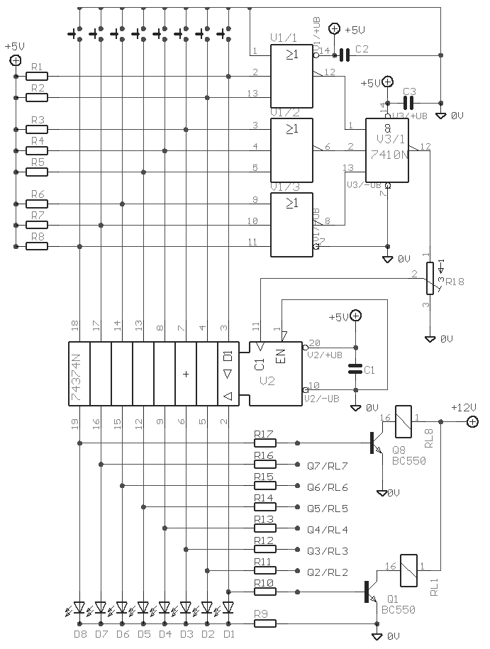
 The Elect. Sel. 8 is a simple circuit, with a choice of 8 sources of any sort ,of 8 independent switches. Each switch corresponding with a relay for example the switch S1 activates the RL1 e.t.c. The uses of the circuit are quite a few, choice of entrances in a sound amplifier, choice of command, in a digital circuit etc. In each entrance a LED which may be independent, except if switches with led are used. 
Circuit diagram

Part list

  • R1-8=10Kohms
  • R9=470 ohms
  • R10-17= 4.7Kohms
  • TR1=4.7Kohms Trimmer
  • IC1=74LS374
  • IC2=74LS27
  • IC3=74LS10
  • T1-8=BC550
  • D1-8=Led 3mm
  • C1-3=47nF 63V MKT
  • RL1-8= 6-12V DC Relay
  • S1-8=Push button SW 
Source http://users.otenet.gr/~athsam/Electronic_sel_8.htm
0 comments

1000Watt Audio Power Amplifier Blazer Circuit

1000Watt Audio Power Amplifier Blazer Circuit
This is a audio power amplifier Blazer circuit provides up to 1000Watt . This fascinating routes several sensible bass and treble alive.
 Importantly ought to opt for Power offer supply, that has been fairly high voltage category 70Vdc GND -70V 10A is that the current low level.

The transistors are 2SC3858 (NPN) and 2SA1494 (PNP), and have high bandwidth, wonderful safe operating space, high linearity and high gain. Driver transistors are 2SC5200 (NPN) and 2SA1943 (PNP). All devices are rated at 230V, with the facility transistors having a 150W dissipation and also the drivers are 50W.

This circuit describes an amplifier, power offer and tests procedures that are all inherently dangerous. Nothing described during this article ought to even be thought-about unless you're totally experienced, grasp specifically what you're doing, and are willing to require full 100% responsibility for what you are doing. There are aspects of the look which will need analysis, fault-finding and/or modification.


0 comments

Connection Tester Circuit Diagram

Description: 
 A low resistance ( 0.25 - 4 ohm) continuity tester for checking soldered joints and connections.

Circuit diagram 
Notes:
 This simple circuit uses a 741 op-amp in differential mode as a continuity tester. The voltage difference between the non-inverting and inverting inputs is amplified by the full open loop gain of the op-amp. Ignore the 470k and the 10k control for the moment, and look at the input of the op-amp. If the resistors were perfectly matched, then the voltage difference would be zero and output zero. However the use of the 470k and 10k control allows a small potential difference to be applied across the op-amp inputs and upset the balance of the circuit. This is amplified causing the op-amp output to swing to full supply voltage and light the LED's. 
Setting Up and Testing:
 The probes should first be connected to a resistor of value between 0.22 ohm and 4ohm. The control is adjusted until the LED's just light with the resistance across the probes. The resistor should then be removed and probes short circuited, the LED's should go out. As the low resistance value is extremely low, it is important that the probes, (whether crocodile clips or needles etc) be kept clean, otherwise dirt can increase contact resistance and cause the circuit to mis-operate. The circuit should also work with a MOSFET type op-amp such as CA3130, CA3140, and JFET types, e.g. LF351. If the lED's will not extinguish then a 10k preset should be wired across the offset null terminals, pins 1 and 5, the wiper of the control being connected to the negative battery terminal. A pin out for the 741 can also be found on my practical section. 

Author: Andy Collinson, anc@mitedu.freeserve.co.uk
Source http://www.zen22142.zen.co.uk/
0 comments

Precision Audio Millivoltmeter

Measures 10mV to 50Volt RMS in eight ranges
Simply connect to your Avo-meter set @ 50uA range
Circuit diagram
Parts:
  • R1 909K 1/2Watt 1% Metal Oxide Resistor
  • R2 90K9 1/2Watt 1% Metal Oxide Resistor
  • R3 9K09 1/2Watt 1% Metal Oxide Resistor
  • R4 1K01 1/2Watt 1% Metal Oxide Resistor
  • R5 100K 1/4W Resistor
  • R6 2M2 1/4W Resistor
  • R7 82K 1/4W Resistor
  • R8 12K 1/4W Resistor
  • R9 1K2 1/4W Resistor
  • R10 3K3 1/4W Resistor
  • R11 200R 1/2W Trimmer Cermet
  • C1 330nF 63V Polyester Capacitor
  • C2,C3 100uF 25V Electrolytic Capacitor
  • C4 220uF 25V Electrolytic Capacitor
  • C5 33pF 63V Polystyrene Capacitor
  • C6 2u2 63V Electrolytic Capacitor
  • D1-D4 1N4148 75V 150mA Diodes
  • IC1 CA3140 Op-amp
  • IC2 CA3130 Op-amp
  • SW1 2 poles 5 ways rotary switch
  • SW2 SPDT switch
  • J1 RCA audio input socket
  • J2,J3 4mm. output sockets
  • B1 9V PP3 Battery
  • Clip for PP3 Battery
Notes:
  • Connect J2 and J3 to an Avo-meter set @ 50uA range
  • Switching SW2 the four input ranges can be multiplied by 5
  • Total fsd ranges are: 10mV, 50mV, 100mV, 500mV, 1V, 5V, 10V, 50V
  • Set R11 to read 1V in the 1V range, with a sinewave input of 1V @ 1KHz
  • Compare the reading with that of another known precision Millivoltmeter or with an The oscilloscope reading must be a sinewave of 2.828V peak to peak amplitude
  • Frequency response is flat in the 20Hz-20KHz range
  • If you have difficulties in finding resistor values for R1, R2, R3 & R4, you can use the following trick:
  • R1 = 10M + 1M in parallel
  • R2 = 1M + 100K in parallel
  • R3 = 100K + 10K in parallel
  • R4 = 1K2 + 6K8 in parallel
  • All resistors 1% tolerance 
Author: RED Free Circuit Designs
Source http://www.redcircuits.com/
0 comments

Photocell based night light

Description.
Many automatic night light circuits had been published here. This one uses a photocell for detecting the light intensity. At full light the resistance of the photocell will be few ten ohms and at darkness it will rise to several hundred ohms. The IC1 uA741 is wired as a comparator here. At darkness the resistance of photocell increases and so the voltage at the inverting input of the IC1 will be less than the reference voltage at the non inverting input. The output of the IC1 goes to positive saturation and it switches ON the transistor to activate the relay. By this way the lamp connected through the relay contact glows. The diode D1 works as a freewheeling diode.
Circuit diagram.

Notes.
  • The circuit can be assembled on a Vero board.
  • Use 9V DC for powering the circuit.
  • POT R7 can be used to adjust the sensitivity of the circuit.
  • The relay K1 can be a 9V, 200 Ohm SPDT type.
  • L1 can be a 230V,60W lamp.
  • R8 can be a ORP 12 photocell.
0 comments

Proximity detector circuit

NE567  tone decoder / PLL IC.

NE567 is a tone decoder IC from Philips. The IC has a built in PLL circuit with AM lock detection and an output driver circuit. The main function of NE567 is to drive a load (usually LED) when a frequency with in its detection band is available at the IC’s input. Center frequency of the input frequency band, output delay etc can be programmed using external components. The features of NE567 IC includes 0.01Hz to 500KHz frequency range, highly stable centre frequency, programmable bandwidth, high noise rejection, can sink 100mA at the output, highly immune to false triggering, externally adjustable VCO frequency etc. The common applications of NE567 are touch tone decoding, remote controls, ultrasonic controls, frequency monitoring etc.

NE567 proximity detector circuit.
 A simple proximity detector circuit using NE567 is shown here. Pin 8 is the output terminal of the internal output driver circuit inside the IC. This pin goes low when the input frequency to the IC (at pin3) is with in the detection band. Resistor R7  and capacitor C4 sets the frequency of oscillations. These oscillations are available at pin 5 and it is coupled to the terminal A of the pick up assembly using capacitor C3. Terminal B picks up the oscillations and couples it to the base of the transistor Q1 through capacitor C1. Q1 and Q2 forms a two stage collector to base biased 2 stage amplifier. R1 and R4 are the collector to base biasing resistors for Q1 and Q2. C2 couples the output of first stage to the second stage. The picked up signal is thus amplified and applied to the input pin (pin3) of the IC through capacitor C7. C6 forms the output filter capacitor and capacitor C5 determines the band width of the receiving signal. C9 is a power supply by pass capacitor. C2 and R2 provides a phase shift to the VCO signal from the IC and this phase shifted signal is detected by the IC. When some object comes near the pick up assembly, the capacitance between its terminals change. This change in capacitance changes the frequency ,IC detects this change and shows the indication.  Resistor R8 limits the output LED current.
 Notes.
  • Use 9V DC for powering the circuit.
  • If you are using an AC adapter, then it must be well regulated and free from noise.
  • The pick up assembly can be made using two metal strips.
  • POT R6 can be used for adjusting the sensitivity.
Source  - http://www.circuitstoday.com/proximity-detector-circuit
0 comments

Voltage follower with 1G ohm input resistance

Circuit diagram 
This circuit uses an LM11 to form a voltage follower with 1G ohm input resistance built using standard resistor values. With the input disconnected, the input offset voltage is multiplied by the same factor as R2; but the added error is small because the offset voltage of the LM11 is so low. When the input is connected to a source less than 1G ohm, this error is reduced. For an ac-coupled input a second 10M resistor could be connected in series with the inverting input to virtually eliminate bias current error; bypassing it would give minimal noise.
 
Author: National Semiconductor
Source http://www.electronics-lab.com/
0 comments

Transmitter FM 45W with valve

TECHNICAL CHARACTERISTICS: 
  • Tendency of catering: 220V AC
  • Frequency of emission at FM: 88~108MHz
  • Force of expense: max 45W (without the R3) 
Circuit diagram
Materially: 

  • R1 15KW/2W
  • R2 1KW/10W
  • R3 1KW/10W (for biggest force in the exit you replace with short-circuit).
  • C1 50pF trimmer
  • C2 30pF trimmer
  • C3 22pF/4KV
  • C4, c6, c9 10nF/1KV
  • C5, c7 1nF/1KV
  • C8 100mF+100mF/450V (Double electrolytic)
  • C9, c10 10nF
  • RFC1, rfc2, rfc3 air Inductors: 15 coils diameter 8mm, from wire 1mm.
  • T1 Transformer 220V/6V-1A
  • T2 Transformer of configuration with being first 4 or 8W
  • T3 Inductor with core ferrite (externally it resembles with small transformer but has a turn only).
  • D1 BY127 rectifier
  • Lamp 807 SYLV USA or EL34 or equivalent
  • ANTENNA Simple dipole L/2. (L= wave length)
  • S1 Main switch of catering.
  • S2 Switch of catering of rise (him we close after zestacej' the thread).
Most elements you can him find in a old back-white television with lamps.
Regulations: 
  • With the C2 we regulate the frequency.
  • With the C1 we adapt the resistance of aerial (practically him we regulate so that it is heard our voice in the radio as long as you become cleaner).
Notes: 
  • The catering better it does not become at straight line from the network 220V but via transformer 220V/220V of isolation and safety 1A.
  • When does not exist the R3, the force of expense is bigger, but respectively is increased also the hum 50Hz, because the simplicity of designing.
  • The control (Audio In) can become from a kasseto'fwno or other powerful source. If it is microphone it will be supposed precedes amplifier so that it acquires a force of order of 8W roughly. 
Author: Kyriakos Kontakos
Source http://www.electronics-lab.com/
0 comments

Simple Touch Switch Circuit

Description
Similar to the CMOS based Touch Switch also on this site, this transistor based touch switch can activate a load simply by the user touching a metal plate. It is designed to directly switch a relay to allow it to be used with large loads. As it uses only a few commonly available transistors and a 12V supply, it is ideal for hostile environments where mechanical switches would be damaged. Using a latching relay and two of these circuits, a simple two pad "touch on/touch off" arrangement can be made. 
Circuit Diagram

Parts


Part

Total Qty.

Description

Substitutions
R1110 Meg 1/4W Resistor
R2147K 1/4W Resistor
R31120k 1/4W Resistor
R41470 Ohm 1/4W Resistor
C1115uF Electrolytic Capacitor
D111N4007 Silicon Rectifier Diode
Q112N5458 N Channel Field Effect Transistor
Q212N2222 NPN Transistor2N3904
Q312N3906 PNP Transistor
K11Relay w/12V Coil, Contacts To Suit Application
MISC1Board, Wire, Small Metal Pad For Touch Pad
Notes

  1. The touch pad can be most easily made by cutting a small square of PCB material and then soldering on a single wire. Alternatively, something like a penny glued to a plastic backing will do the job.
  2. As mentioned, a latching relay can be used so that a momentary touch activates the relay and it remains active. To turn off a latching relay, power must be interrupted. So a 2nd circuit with a normal relay can be used to cut power (use the NC contacts on the 2nd circuit). Placed side by side, two touch pads form an "on" and an "off" pad.
Source - http://www.aaroncake.net/circuits/Simple_Touch_Switch_Circuit.asp
0 comments

Police siren using NE555

Description.
A lot of electronic circuits using NE555 timer IC are already published here and this is just another one.Here is the circuit diagram of a police siren based on NE55 timer IC. The circuit uses two NE555 timers ICs and each of them are wired as astable multivibrators.The circuit can be powered from anything between 6 to 15V DC and is fairly loud.By connecting an additional power amplifier at the output you can further increase the loudness.
IC1 is wired as a slow astable multivibrator operating at around 20Hz @ 50% duty cycle and IC2 is wired as fast astable multivibrator operating at around 600Hz.The output of first astable mutivibrator is connected to the control voltage input (pin5) of IC2. This makes the output of IC2 modulated by the output frequency of IC1, giving a siren effect. In simple words, the output frequency of IC2 is controlled by the output of IC1.
 Circuit diagram.


Notes.
  • The circuit can be assembled on a Perf board.
  • I used 12V DC for powering the circuit.
  • Instead of using two NE55 timer ICs, you can also use a single NE556 timer.
  • NE556 is nothing but two NE555 ICs in one package.
  • Refer the datasheets of NE555 and NE556 to have a clear idea.
  • Speaker can be a 64ohm, 500mW one.
Source - http://www.circuitstoday.com/police-siren-using-ne555
0 comments

Remote Control Circuit Through RF Without Microcontroller

Description 
This is a simple type remote control by using RF communication without microcontroller. In this project a remote has been designed for various home appliances like television, fan, lights, etc. It gives lot of comfort to the user since we can operate it by staying at one place. We can control any of the appliances by using this remote within the range of 400 foots. In this project consist of two sections, transmitter (remote) and receiver section. Whenever we are pressing any key in the remote it generates the corresponding RF signals, and these signals are received by the receiver unit. ASK transmitter and receiver is used as transmitter and receiver. HT12E, HT12D encoders and decoders are used in this electronic circuit. The block digram of the whole circuit is given below.
 Appliance Control Block Diagram

Remote Section
In remote section consist of an encoder (HT 12E) and a ASK transmitter. The encoder generates 8 bit address and 4bit data. We can set the address by using the DIP switch connected in A0 to A7 (pin 1 to 8 ) encoder. If we set an address in the remote section, the same address will be required in the receiver section. So always set same address in transmitter and receiver. Whenever we press any key in the remote the encoder generates corresponding 4bit data and send this data with 8bit address by using ASK transmitter. The transmitting frequency is 433MHz. The transmitter output is up to 8mW at 433.92MHz with a range of approximately 400 foot (open area) outdoors. Indoors, the range is approximately 200 foot. 
Remote or Transmitter Circuit

Receiver Section
 At the receiver section ASK receiver is present. The receiver also operates at 433.92MHz, and has a sensitivity of 3uV.  The ASK receiver operates from 4.5 to 5.5 volts-DC, and has both linear and digital outputs. It receives the datas from the transmitter. Then the decoder (HT 12D) decodes the date and it will enable the corresponding output pin (pin 10,11,12,13). Each output pins are connected to separate flip flops. The output of encoder will change the state of the flip flop. So its output goes to set (high) from reset (low) state. This change makes a high signal in the output of the flip flop. This output signal is not capable to drive a relay directly. So we are using current driver, SL100 transistor act as the current driver. The appliance is connected to 230V AC through the relay and the appliance will start. The relay will be re-energized when the same switch is pressed in the remote. This is because we are pressing the same switch in the remote control. The output of the decoder again goes to high so this signal will again change the state of the flip flop. So, the relay gets re-energized and the appliance goes to OFF state.
 Remote Control Receiver Circuit

Components Used 

IC HT 12D 1
CD 4017 4
LM 7805 2
TRANSISTOR BC 558 4
SL 100 4
RESISTOR 180 K 4
1 K 4
560 E 4
39K 1
1M 1
CAPACITOR 100nF 4
100MFD/16V 4
LED RED 4
DIP SWITCH 2
PUSH TO ON SWITCH 4
ASK TRANSMITER 433MHZ 1
ASK RECEIVER 433MHZ 1
Source - http://www.circuitstoday.com/remote-control-circuit-through-rf-without-microcontroller
0 comments
 
Support : Creating Website | Johny Template | Mas Template
Copyright © 2011. The Circuit - All Rights Reserved
Template Created by Creating Website Published by Mas Template
Proudly powered by Blogger